Hotline
0903 999 763Danh mục sản phẩm
Nhà sản xuất

Biến tần thế hệ mới với nhiều tính năng vượt trội:
- Tiết kiệm năng lượng
- Nhiều tính năng cho quạt và bơm
- Bảo mật và an toàn
- Dễ dàng cài đặt và vận hành
Energy Saving with Inverters
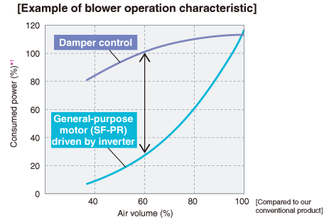
The consumed power of a variable-torque load, such as fans, pumps, and blowers, is proportional to the cube of its rotation speed.
Adjusting the air volume by the inverter rotation speed control can lead to energy savings.

*1: Rated motor output is 100%
Utilizing the motor capability to the full
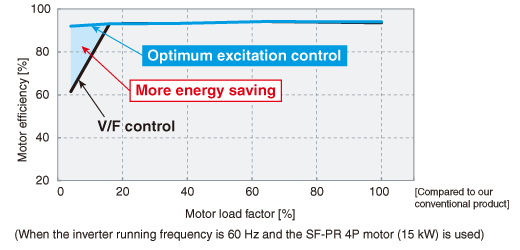
Optimum excitation control
● Optimum excitation control continuously adjusts the excitation current to an optimum level to provide the highest motor efficiency. With a small load torque, a substantial energy saving can be achieved.
For example, at 4% motor load torque for a general-purpose motor, the motor efficiency under Optimum excitation control is about 30% higher than the motor efficiency under V/F control.

System cost reduction
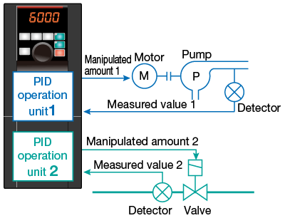
Two PID operation units are available in the inverter. The inverter can perform PID control of the motor operation and control the external equipment at the same time. The system cost can be reduced because no external PID controller is required for controlling the external equipment.

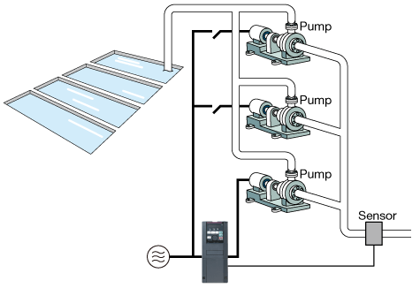
Multi-pump function
By controlling the pumps connected in parallel (up to four pumps) by the PID control by one inverter, water volume, etc. can be adjusted.
One of the connected pumps is driven by the inverter. Other pumps are driven by commercial power supply. The number of pumps to be driven by commercial power supply is automatically adjusted according to the water volume.
*Source: mitsubishielectric.com
Specifications
|
Control method
|
Soft-PWM control, high carrier frequency PWM control (selectable among V/F control (Optimum excitation control), Advanced magnetic flux vector control (Advanced optimum excitation control), and PM motor control) |
|
|
Starting torque |
Induction motor |
120% 0.5 Hz (Advanced magnetic flux vector control) |
|
IPM motor |
50% |
|
|
Output frequency range
|
0.2 to 590 Hz (Up to 400 Hz with Advanced magnetic flux vector control, and PM motor control.) |
|
|
Regenerative braking torque (Maximum value/ permissible duty) |
Induction motor |
0.75K to 55K····15% continuous, 75K or higher····10% continuous |
|
IPM motor |
Approximately 5% (1.5K or lower····Approximately 10%)*1 |
|
|
Acceleration/deceleration time setting |
0 to 3600 s (up to three types of accelerations and decelerations can be set individually.) |
|
|
Multi-speed |
15 speeds |
|
|
Speed command
|
0 to 5 VDC, 0 to 10 VDC, 0 to ±5 VDC, 0 to ±10 VDC, 4 to 20 mA, pulse train input digitally set with operation panel or parameter unit, 4-digit BCD or 16-bit binary (when using optional FR-A8AX) |
|
|
Alarm output |
1 changeover contact (230 VAC, 0.3 A, 30 VDC, 0.3 A), open collector output, alarm code (4-bit) output |
|
|
Output signal
|
Five types of open collector outputs and two types of contact outputs (1 changeover contact) can be selected from inverter running, up to frequency, frequency detection, operation ready, overload warning, error output and alarm, etc. |
|
|
Monitor function |
One monitored item can be selected from output frequency, motor current (steady or peak value), output voltage, operation speed, converter output voltage, input power, output power and load meter, etc. Pulse train output (1440 pulses/s 2 mA) and analog output (0 to 10 VDC) |
|
|
Restart after instantaneous power failure |
Available (reduced voltage method (frequency search selectable)) |
|
|
Removable terminal block |
Used for control circuit terminals |
|
|
Communication function |
RS-485 supported (Mitsubishi inverter protocol, MODBUS ® RTU) as standard, CC-Link, CC-Link IE Field Network, PROFIBUS-DP, DeviceNet™ options available |
|
Bản quyền thuộc về CÔNG TY CỔ PHẦN CÔNG NGHỆ HỢP LỰC. Phát triển bởi LYLE SOFTWARE


